Raw synthesis gas (syngas) from the high temperature gas cooling (HTGC) system needs to be cleaned to remove contaminants including fine particulates, sulfur, ammonia, chlorides, mercury, and other trace heavy metals to meet environmental emission regulations, as well as to protect downstream processes. In the case of carbon sequestration, carbon dioxide (CO2) is also removed. Depending on the application, syngas may need to be conditioned to adjust the hydrogen-to-carbon monoxide (H2-to-CO) ratio to meet downstream process requirement. In applications where very low sulfur (<10 ppmv) syngas is required, converting carbonyl sulfide (COS) to hydrogen sulfide (H2S) before sulfur removal may also be needed. Typical cleanup and conditioning processes include cyclone and filters for bulk particulates removal; wet scrubbing to remove fine particulates, ammonia and chlorides; solid absorbents for mercury and trace heavy metal removal; water gas shift (WGS) for H2-to-CO ratio adjustment; catalytic hydrolysis for converting COS to H2S; and acid gas removal (AGR) for extracting sulfur-bearing gases and CO2 removal.
Fine Particulate Removal
Raw syngas leaving the HTGC system in today's commercial gasification plant is normally quenched and scrubbed with water in a trayed column for fine char and ash particulate removal prior to recycle to the slurry-fed gasifiers. For dry feed gasification, cyclones and candle filters are used to recover most of the fine particulate for recycle to the gasifiers before final cleanup with water quenching and scrubbing. In addition, fine particulates, chlorides, ammonia, some H2S, and other trace contaminants are also removed from the syngas during the scrubbing process. The scrubbed gas is then either reheated for COS hydrolysis and/or a sour WGS when required, or cooled in the low temperature gas cooling (LTGC) system by generating low pressure steam, preheating boiler feed water, and heat exchanging it against cooling water before further processing.
Spent water from the scrubber column is directed to the sour water treatment system, where it is depressurized and decanted in a gravity settler to remove fine particulates. Solid-concentrated underflows from the settler bottom are filtered to recover the fine particulate as the filter cake, which is then either discarded or recycled to the gasifier depending on its carbon content. Water from the settler is recycled for gasification uses with the excess being sent to the wastewater treatment system for disposal.
Mercury and Trace Elements
Current commercial practice is to pass cooled syngas from LTGC through sulfided, activated carbon beds to remove over 90% of the mercury and a significant amount of other heavy metal contaminants. Due to the sulfur in the activated carbon, these beds are normally placed ahead of the AGR system to minimize the possibility of sulfur slipping back into and contaminating the cleaned syngas.
Newer regulations are demanding increased levels of mercury reduction as well as that of other toxic species present in syngas, which may require increasing sophistication in technology to remove these contaminants.
ACID GAS REMOVAL (AGR)
Operation
Acid gases produced in gasification processes mainly consist of hydrogen sulfide (H2S), carbonyl sulfide (COS), and carbon dioxide (CO2). Syngas exiting the particulate removal and gas conditioning systems, typically near ambient temperature at 100°F, needs to be cleaned of the sulfur-bearing acid gases to meet either environmental emissions regulations, or to protect downstream catalysts for chemical processing applications. For integrated gasification combined cycle (IGCC) applications, environmental regulations require that the sulfur content of the product syngas be reduced to less than 30 parts per million by volume (ppmv) in order to meet the stack gas emission target of less than 4 ppmv sulfur dioxide (SO2)1. In IGCC applications, where selective catalytic reduction (SCR) is required to lower NOx emissions to less than 10 ppmv, syngas sulfur content may have to be lowered to 10 to 20 ppmv in order to prevent ammonium bisulfate fouling of the heat recovery steam generator's (HRSG) cold end tubes. For fuels production or chemical production, the downstream synthesis catalyst sulfur tolerance dictates the sulfur removal level, which can be less than 0.1 ppmv.
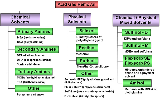
Conventional processes for removing acid gases typically involve their countercurrent absorption from the syngas using a regenerative solvent in an absorber column. This process approach of gas-liquid contacting to remove acid gases is very commonly used in a wide range of process industries, including refining, chemicals, and natural gas production. However, because of the significantly different required degrees of acid gas removal that depend on the application, the choice of solvents varies significantly:
- For chemical synthesis applications which require syngas with less than 1 ppmv sulfur, physical solvent processes such as Rectisol and Selexol are normally used which allow essentially total removal of sulfur; these may operate at depressed temperatures (Rectisol operates at -40°C).
- For power generation applications, which allow higher sulfur levels (approximately 10 to 30 ppmv sulfur), chemical solvent processes such as Methyl diethanolamine (MDEA) are normally used. Many but not all of these utilize amine-type solvents.
- Mixtures of chemical and physical solvents, also known as hybrid or composite solvents are also possible; Sulfinol is a well-known example.
Acid Gas Removal Technologies
In both physical and chemical absorption processes, the syngas is washed with lean solvent in the absorber to remove H2S. Cleaned syngas is sent to downstream systems for further processing. Acid gas-rich solvent leaving the bottom of the absorber is sent to the regenerator, where the solvent is stripped with steam under low pressure (reboiling) to remove the absorbed sulfur. The concentrated acid gas stream, rich in H2S, exits the top of the regenerator and is sent to the Sulfur Recovery Unit (SRU) for sulfur recovery. The SRU consists of a Claus plant, in which the H2S is converted to sulfur, a salable byproduct. The regenerated lean solvent from the bottom of the regenerator is cooled by a heat exchanger against the rich solvent, followed by water cooling before being recycled back to the top of the absorber to start the absorption process cycle again.
The physical solvent processes tend to co-absorb more CO2 than chemical/amine processes such as MDEA. Multiple step depressurization of the rich solvent, supplemented with nitrogen stripping, is employed by the physical solvent processes to reject sufficient CO2 to concentrate the acid gas from the regenerator overhead to at least 15 to 25 volume% H2S in order to feed the Claus SRU.
Because of the need for refrigeration (e.g. Rectisol), and in general more complex solution flashing arrangements, physical solvent processes are two to three times more costly than chemical solvent processes. While the physical solvent processes have higher power consumption than the chemical solvent processes, the chemical processes have higher steam consumption which translates to reduced power output from the power train. Thus, impact on overall net power output may be similar between the two types of AGR processes.
Depending on the solvent used, COS may first need to be converted to H2S via a COS hydrolysis unit. Also, it is important to note that H2S and CO2 can be removed either simultaneously or selectively, depending on the raw syngas composition and conditions, and the end syngas specifications.
Chemical Solvents
Chemical solvents include primary, secondary and tertiary amines, and alkaline salts such as potassium carbonate. Through acid-base reactions, aqueous solutions of these basic compounds capture and remove acid gases by forming weak chemical bonds with dissolved acid gases in the absorber. The bonds are broken by heat in the regenerator to release the acid gases and regenerate the solvent for reuse. Chemical solvent absorption processes normally operate at slightly above ambient temperature. Chemical solvents are more effective for low acid gas partial pressure applications than physical solvents.
Physical Solvents
Physical solvents are organic solvents that have a high affinity for acid gases. In general, the physical solvents demand relatively high syngas pressures, high partial pressure of the acid gases, and/or low operating temperature in the absorber (in some cases cryogenic temperatures below –150°C, –238°F or 123 K), for good performance. Solvent, rich with acid gases from the absorber, is then subjected to multistage controlled pressure decreases, followed with hot stripping in the regenerator, to release the acid gases and regenerate the solvent for reuse.
Mixed Solvent Systems
Mixtures of amine chemical solvents and physical solvents take advantage of the high treated-gas purity performance of chemical solvents, and the low energy requirement associated with flash regeneration of physical solvents. In general, such mixtures are effective over a wide range of acid gas partial pressures at near-room temperatures, allowing both improved acid gas absorption at high partial pressures, and with the amine portion allowing AGR under very low partial pressures as the case may be. Also, they feature higher solubility of COS and organic sulfur compounds than aqueous amines alone.
Applications
There are over 30 AGR processes available commercially, but only four of these have been demonstrated or implemented in the 18 commercial-size coke or coal-based gasification plants worldwide, as reported by SFA Pacific in 2002:2 Rectisol, Selexol, Sulfinol, and MDEA. Half of these18 plants are for liquid fuels, methanol, SNG or ammonia production, while the other half are IGCC applications.
Eight of the nine chemical production plants, in operation as of 2002, use Rectisol (typically operates at -40°F to -80°F), and one uses Selexol (typically operates at 20°F to 40°F). This is consistent with the general perception that physical solvent-based AGR is normally selected to protect synthesis catalysts against poisoning from sulfur and other trace contaminants in chemical production from coal applications. While Rectisol is more costly, it is preferred for treating coal-based syngas because it allows for very deep sulfur removal (<0.1 ppmv H2S plus COS), and also because it can remove HCN, NH3, and many metallic trace contaminants (including iron- and nickel-carbonyls, and mercury) to provide additional catalyst protection.
SULFUR RECOVERY AND TAIL GAS TREATING
Sulfur is a component of coal and other gasification feed stocks. Resulting sulfur compounds in syngas need to be removed in most gasification applications due to environmental regulations or to avoid catalyst poisoning. Whether it is electricity, liquid fuels, or some other product being output, sulfur emissions are regulated, and sulfur removal is important for this reason, along with the prevention of downstream component fouling. In addition to these constraints, recovering saleable sulfur is an important economic benefit for a gasification plant.
To illustrate the previous point, in 2011 8.1 million tons of elemental sulfur was produced, with the majority of this coming from petroleum refining, natural gas processing and coking plants. Total shipments were valued at $1.6 billion, with the average mine or plant price of $200 per ton, up from $70.48 in 2010. Prices have fluctuated in recent years, but price of sulfur in 2014 has still been well over $150 per ton. The United States currently imports sulfur (36% of consumption, mostly from Canada), meaning the market can support more domestic sulfur production.
USGS Mineral Commodity Information: Sulfur
In a typical design, a series of process steps is used to recover sulfur as a useful by-product from gasification processes. First, cooled syngas/feed gas is contacted with a chemical solvent in an absorber unit, where, as the gas passes through, almost all of the hydrogen sulfide (H2S) and some carbon dioxide (CO2) are removed in the basic acid gas removal (AGR) process. The solvent is now rich with H2S and it moves on to a stripping unit to clean and recycle the solvent and separate the H2S. The basic stripping process and solvent stripping/regeneration are depicted below.
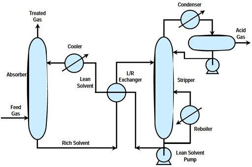
Simplified Diagram of the AGR Process
The sulfur-containing acid gases removed by the AGR process consist primarily of a mixture of hydrogen sulfide (H2S) and carbon dioxide, which is inevitably captured along with the H2S to some degree. This serves as feed gas to a sulfur recovery process, in which sulfur is recovered as either liquid or solid elemental sulfur, or as sulfuric acid, depending on market demands. For an elemental sulfur product, a Claus sulfur recovery unit produces elemental sulfur from H2S in a series of thermal stage followed by multiple catalytic stages, achieving about 98% recovery of the sulfur in the syngas. Part of the H2S is oxidized to produce sulfur dioxide (SO2), which is then reacted with the remaining H2S to give elemental sulfur and water. Tail gas from the Claus process is sent for further treatment to a Tail Gas Unit (TGU), which may be exemplified by the amine-based Shell Claus Off-gas Treatment (SCOT) unit. The SCOT unit removes nearly all of the remaining sulfur—in the form of a tail-gas stream of unreacted sulfur, H2S, SO2, and carbonyl sulfide (COS)—that the Claus unit misses. The SCOT unit uses a cobalt-molybdenum catalyst to convert SO2 to H2S, which is then removed in an absorber. Altogether, this process series approach can achieve a typical overall sulfur recovery of 99.8%.
Sulfuric acid synthesis is an alternative to sulfur recovery via the Claus process. This may be preferred if the plant is located close to a sizeable market for sulfuric acid. In this case, H2S is first burned in a furnace to form SO2, which is then converted to sulfur trioxide (SO3), which is then scrubbed with water or a recycled weak sulfuric acid stream to yield saleable 98% sulfuric acid. Typically, 99.8% of the H2S can be recovered in a sulfuric acid plant.
PARTICULATE REMOVAL
Background
Particulate matter (PM) consists of microscopic solid particles or liquid droplets which are small enough to enter the lungs and cause health problems. Both nitrogen oxides (NOx) and sulfur oxides (SOx) are associated with the formation of particulate matter, but other processes can contribute to their formation. Aside from health concerns, particulates cause reduced visibility and haze when released in the atmosphere.
Ash is formed in coal combustion and gasification from inorganic impurities in the coal. Some of these impurities react to form microscopic solids which can be suspended in the exhaust gases in the case of combustion, or the syngas produced by gasification. In the latter case, raw syngas leaving the gasifier contains fine ash and/or slag that needs to be removed prior to sending the gas downstream for further processing. The bulk of the particulates are removed using dry particulate removal systems such as filters and/or cyclones. High temperature ceramic filters have been developed for gasification applications and are currently commercially available. The recovered fly ash/slag can either be recycled to the gasifier or purged from the system as a byproduct. The syngas leaving the dry particulate removal system is then further purified by passing through a wet scrubber where any residual solids can be removed down to a 1 ppm level.
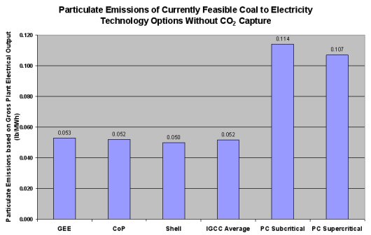
Gasification offers two main advantages in particulate control over combustion processes. First, gasification of coal provides the capability of removing most of the ash as inert slag or bottom ash for disposal or sale as a byproduct. Second, since the syngas leaving the gasifiers is much more dense than combustion exhaust gases, the particulate matter can more easily be removed. The following figure gives an indication of the advantage that gasification has for particulate emissions.
Dry Particulate Removal
Bulk solid particulate removal can be achieved with either filters and/or cyclones, depending on the gasification system and operating conditions. Cyclones are a commercially proven technology and can be refractory-lined for high temperature operations. High temperature candle filters have been developed and can remove particulates from raw syngas at temperatures between 550°F and 900°F (~ 300°C to 500°C). Below 550°F, the filters may be blinded by deposits of ammonium chloride. Above 900°F, alkali compounds may pass through the filters at unacceptable levels, as the vapor pressures of these compounds may still be high. Development of candle filters that can remove particulates at high temperatures is a significant technology development for gasification. Use of candle filters in dry solids removal systems is now considered commercially available technology. In some current gasification designs, candle filters are being used upstream of a wet scrubber for effective overall solids removal.
Effective dry particulate removal is an integral part of the warm gas cleanup (WGCU) technology development effort being undertaken by Research Triangle Institute (RTI) with funding from the Department of Energy (DOE).
Wet Scrubbing
In most commercial gasification operations, syngas leaving the filter is quenched and scrubbed with water for final particulate removal. Water scrubbing takes place below the dew point temperature of the syngas so that the finest solid particles can act as nuclei for condensation, thus ensuring that all solids can be removed efficiently. Scrubbing also removes chlorides, ammonia, some hydrogen sulfide (H2S) and other trace contaminants from the syngas. Typically, the scrubbed syngas is reheated for carbonyl sulfide (COS) hydrolysis and/or a sour water gas shift (WGS) if required, followed by cooling in a low temperature gas cooling (LTGC) system to generate low pressure steam. After these processes, the syngas is sent downstream for sulfur and mercury removal.
Spent water from the scrubber column is directed to a gray water treatment system where it is depressurized and vacuum flashed. The spent water is then decanted into a gravity settler to remove particulates. Solid-concentrated underflows from the settler bottom are filtered to recover the fine particulate as a filter cake, which is then either discarded or recycled to the gasifier depending on its carbon content. Water from the settler is recycled for gasification reuse, with excess being sent to the wastewater treatment system for disposal.
